7 Ways to Field Test GPS Accuracy with Control Points
Why it matters: GPS accuracy can make or break critical surveying projects but manufacturers’ specs don’t always match real-world performance. You need reliable field testing methods to verify your equipment’s precision before staking your reputation on the data.
The bottom line: Control points offer the gold standard for GPS accuracy validation by providing known reference positions that eliminate guesswork from your testing process.
Disclosure: As an Amazon Associate, this site earns from qualifying purchases. Thank you!
Understanding GPS Accuracy and Control Points Fundamentals
GPS accuracy testing requires precise reference points to validate your equipment’s performance. Control points serve as the foundation for reliable field testing protocols.
P.S. check out Udemy’s GIS, Mapping & Remote Sensing courses on sale here…
Achieve a flawless, even complexion with e.l.f. Flawless Satin Foundation. This lightweight, vegan formula provides medium coverage and a semi-matte finish for all-day wear, while hydrating your skin with glycerin.

What Are Control Points and Why They Matter
Control points are precisely surveyed locations with known coordinates that serve as reference benchmarks for GPS accuracy testing. You’ll use these fixed positions to compare your GPS readings against established ground truth data. Professional surveyors rely on control points because they eliminate guesswork from accuracy assessments. The National Geodetic Survey maintains thousands of control points across the United States with centimeter-level precision. Control points provide the only reliable method to quantify GPS positional errors in real-world conditions.
Types of GPS Accuracy Measurements
GPS accuracy measurements fall into three primary categories: horizontal accuracy, vertical accuracy, and timing precision. Horizontal accuracy measures your position’s deviation from true coordinates in the X-Y plane, typically expressed in meters or feet. Vertical accuracy determines elevation errors compared to known heights above sea level or ellipsoid surfaces. Circular Error Probable (CEP) represents the most common horizontal accuracy metric, indicating the radius containing 50% of position measurements. Real-Time Kinematic (RTK) systems achieve centimeter-level accuracy, while standard GPS receivers typically provide 3-5 meter precision.
Common Sources of GPS Error
GPS errors originate from atmospheric interference, satellite geometry, and receiver limitations that affect positional accuracy. Ionospheric delays occur when GPS signals pass through charged particles in the upper atmosphere, creating timing errors. Multipath interference happens when GPS signals bounce off buildings, terrain, or vegetation before reaching your receiver. Dilution of Precision (DOP) values indicate satellite geometry quality, with lower numbers representing better positioning conditions. Clock errors between satellites and receivers introduce timing discrepancies that translate to positional mistakes. Selective Availability, though discontinued, historically degraded civilian GPS accuracy through intentional signal degradation.
Selecting Appropriate Control Points for Testing
You’ll need to carefully choose control points that provide reliable reference coordinates for your GPS accuracy testing. The quality of your control points directly impacts the validity of your test results.
Identifying Surveyed Benchmarks and Monuments
Survey monuments offer the most reliable reference points for GPS accuracy testing because they’re professionally established with known coordinates. You can locate these permanent markers through local surveying firms or municipal engineering departments.
Make bold, lasting marks with Sharpie Permanent Markers. This set of five black fine-tip markers features quick-drying, fade-resistant ink that works on various surfaces like paper, plastic, and metal.

Bronze disks, concrete monuments, and steel rods represent common benchmark types you’ll encounter in the field. These markers typically display identification numbers and coordinate information engraved directly on the surface. Check with your county surveyor’s office to access records showing monument locations and their established coordinates before conducting your field tests.
Using National Geodetic Survey Control Points
National Geodetic Survey (NGS) control points provide centimeter-level accuracy across the United States through their continuously operating reference station network. You can search the NGS database online using your testing area’s coordinates to find nearby control points.
Download the official datasheets for each control point before your field visit to verify coordinates and monument condition. The NGS maintains over 300,000 control points with coordinates referenced to the North American Datum of 1983 (NAD 83). Always verify that the physical monument matches the datasheet description to ensure you’re testing at the correct location.
Creating Your Own Reference Points
Establishing custom reference points requires high-precision surveying equipment when existing control points aren’t available in your testing area. You’ll need a total station or RTK GPS system with sub-centimeter accuracy to create reliable reference coordinates.
Measure distances accurately with the NorthWest Instrument NTS03 Total Station. This reflectorless instrument offers 2-second accuracy for precise surveying.

Occupy your reference point location for at least 30 minutes using static GPS observations to achieve the necessary precision. Mark the point with a permanent monument like a concrete marker or steel pin to ensure repeatability in future tests. Document the coordinates in multiple datums and include detailed site descriptions for future reference during your GPS accuracy assessments.
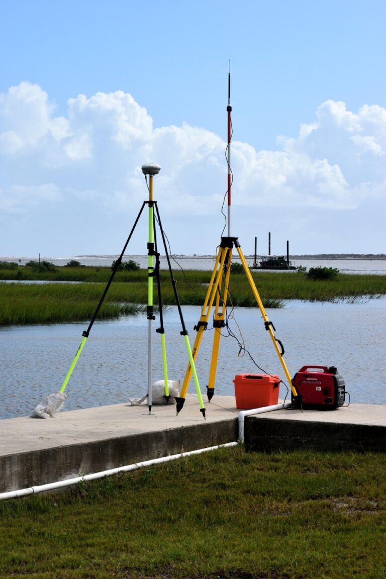
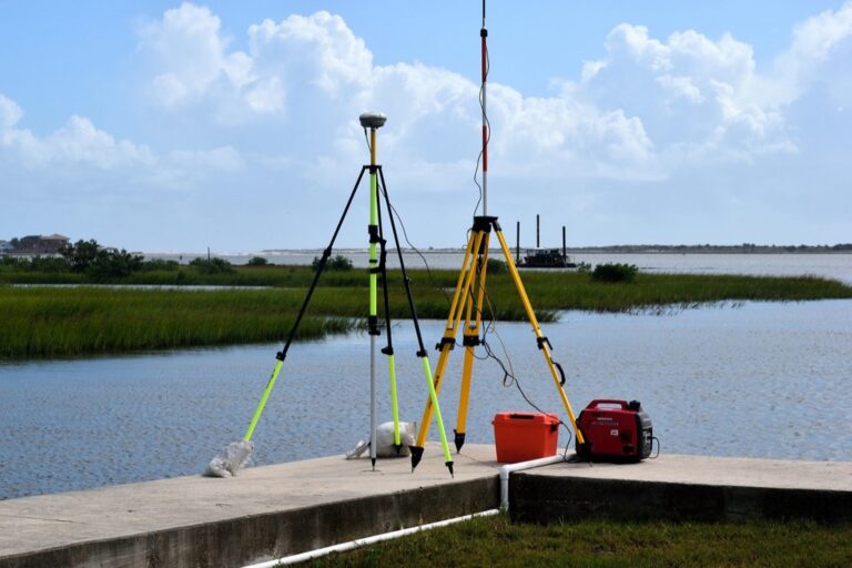
Gathering Essential Equipment for Field Testing
You’ll need the right combination of GPS equipment and supporting tools to conduct reliable accuracy assessments at your control points.
Achieve centimeter-level precision with the E1 RTK GNSS system, featuring a 5km radio range and 60° tilt surveying. Enjoy 20+ hours of continuous operation and robust signal tracking in challenging environments.

GPS Receivers and Device Selection
Get fast, accurate GPS positioning for your laptop, PC, car, or boat with this USB receiver. It features a high-performance chip for multi-GNSS support and a magnetic base for easy installation.

Choose GPS receivers that match your accuracy requirements for meaningful field testing results. Professional handheld units like Garmin GPSMAP 66sr or Trimble Geo 7X provide sub-meter accuracy capabilities with detailed logging functions. Consumer smartphones typically achieve 3-5 meter accuracy under ideal conditions but lack the precision needed for rigorous control point validation. Multi-constellation receivers supporting GPS, GLONASS, Galileo, and BeiDou systems deliver more reliable position fixes in challenging environments.
Survey-Grade vs Consumer-Grade Equipment
Survey-grade equipment delivers centimeter-level accuracy through advanced signal processing and correction capabilities. RTK-enabled receivers like Trimble R10 or Leica GS18 can achieve 1-2 centimeter horizontal accuracy when connected to base stations or correction services. Consumer-grade devices rely on basic positioning algorithms without differential corrections, limiting their usefulness for precise control point testing. Survey equipment costs significantly more but provides the measurement quality necessary for professional accuracy validation work.
Additional Tools and Accessories Needed
Essential accessories enhance data collection reliability during your control point testing sessions. Bring extra batteries, weather protection cases, and sturdy tripods or range poles for consistent receiver positioning. Digital cameras document monument conditions and site characteristics for your testing records. Handheld compasses, measuring tapes, and field notebooks help verify control point descriptions and record environmental factors. Consider portable weather stations to monitor atmospheric conditions that might affect GPS signal quality during your accuracy assessment.
Planning Your GPS Accuracy Field Test
Strategic planning ensures your GPS accuracy assessment produces reliable, actionable results. You’ll need to coordinate multiple variables including location selection, environmental conditions, and testing procedures.
Determining Test Locations and Routes
Select test locations that represent your typical working conditions and operational requirements. Choose control points within your project area whenever possible to match the environmental factors you’ll encounter during actual fieldwork. Plan efficient routes between multiple control points to maximize data collection while minimizing travel time. Consider accessibility factors such as vehicle parking, walking distances, and terrain challenges that might affect your testing schedule. Document each location’s characteristics including vegetation cover, nearby structures, and potential interference sources.
Weather Conditions and Timing Considerations
Schedule your testing during stable atmospheric conditions to minimize ionospheric interference and signal degradation. Avoid testing during severe weather events, solar storms, or periods of high atmospheric activity that can affect GPS signal propagation. Plan morning sessions when possible, as atmospheric conditions are typically more stable before midday heating begins. Monitor space weather forecasts and solar activity indices to identify optimal testing windows. Allow extra time for repeated measurements at each control point to account for changing satellite geometry throughout the day.
Creating a Systematic Testing Protocol
Develop a standardized procedure that ensures consistent data collection across all test locations. Establish specific measurement durations, such as 5-minute observation periods, and determine the number of repetitions needed for statistical validity. Create data recording sheets that capture essential information including control point coordinates, GPS readings, time stamps, and environmental conditions. Define quality control checkpoints throughout your testing process to identify and address potential issues before they compromise your results. Document your methodology thoroughly to enable future replication and comparison of test results.
Conducting the GPS Accuracy Field Test
Execute your field test systematically at each control point to gather reliable accuracy data. Follow consistent procedures across all test locations to ensure valid comparisons.
Setting Up at Each Control Point
Position your GPS receiver directly over the control point monument using a surveying tripod or bipod for stability. Ensure the antenna remains level and secure throughout the measurement period. Check that satellite reception isn’t obstructed by buildings, trees, or other structures that could interfere with signal quality. Allow the receiver to initialize and achieve satellite lock before beginning data collection.
Recording Multiple Position Readings
Collect at least 10-15 position readings at each control point over a minimum 5-minute observation period. Record coordinates every 30 seconds to capture temporal variations in GPS accuracy. Document the number of satellites tracked, HDOP values, and signal strength indicators for each measurement. Save raw data files when possible to enable post-processing analysis and verification of field results.
Documenting Environmental Factors
Record weather conditions including temperature, humidity, and atmospheric pressure at each test location. Note nearby obstructions such as buildings, power lines, or dense vegetation that might cause multipath interference. Photograph the setup and surrounding environment to document potential sources of GPS error. Log the exact time of day for each measurement session to correlate with satellite constellation geometry.
Calculating and Analyzing GPS Accuracy Results
Now that you’ve collected GPS data at control points, you need to transform raw measurements into meaningful accuracy metrics. This analysis reveals how well your GPS equipment performs under real-world conditions.
Measuring Horizontal and Vertical Errors
Calculate horizontal error by finding the distance between your GPS reading and the control point’s known coordinates using the Pythagorean theorem. Vertical error represents the absolute difference between measured elevation and established height values. Record both error types in meters or feet for each test point, noting that horizontal accuracy typically outperforms vertical accuracy by a factor of 2-3 in most GPS receivers.
Computing Root Mean Square (RMS) Values
Compute RMS error by squaring each individual error measurement, calculating the mean of squared values, then taking the square root of that result. This statistical measure provides a single accuracy value that accounts for all test points while giving greater weight to larger errors. RMS values help you compare equipment performance and determine if your GPS meets project specifications for positional accuracy.
Identifying Patterns in Accuracy Variations
Examine your error data for systematic patterns that indicate specific performance issues or environmental influences. Look for directional bias in horizontal errors, elevation-dependent vertical errors, or time-based accuracy degradation throughout your testing period. Document correlations between accuracy variations and factors like satellite geometry, atmospheric conditions, or proximity to reflective surfaces that could affect future GPS operations in similar environments.
Interpreting Your GPS Field Test Data
Understanding your GPS field test results requires comparing measured positions against control point coordinates to determine accuracy performance. This analysis reveals whether your equipment meets project specifications and identifies potential issues affecting data quality.
Understanding Acceptable Accuracy Ranges
Acceptable GPS accuracy ranges depend on your specific application requirements and equipment specifications. Survey-grade receivers typically achieve horizontal accuracy within 1-3 meters for autonomous positioning, while differential GPS systems can reach sub-meter precision. Consumer-grade devices generally perform within 3-5 meters under ideal conditions. You’ll need to establish tolerance thresholds based on your project’s precision requirements, considering that vertical accuracy is typically 1.5 times less precise than horizontal accuracy due to satellite geometry limitations.
Comparing Results to Manufacturer Specifications
Manufacturer specifications provide baseline expectations for your GPS equipment‘s performance under ideal conditions. Compare your field test results against published accuracy statements, noting that manufacturers often report best-case scenarios with clear sky views and minimal interference. Your real-world results may show 2-3 times larger errors due to environmental factors like tree cover, buildings, or atmospheric conditions. Document any significant deviations from specifications, as consistent underperformance may indicate equipment calibration issues or the need for differential correction services.
Recognizing When Additional Testing Is Needed
Additional testing becomes necessary when your results show inconsistent patterns or exceed acceptable error thresholds. Conduct extended testing if you observe accuracy variations greater than 50% between different control points or if vertical errors consistently exceed horizontal errors by more than 2:1 ratios. You should also perform supplementary tests when environmental conditions during initial testing weren’t representative of typical working conditions, or when equipment modifications like firmware updates or antenna changes occur after your original assessment.
Improving GPS Accuracy Based on Test Results
Once you’ve analyzed your field test data you can implement specific improvements to enhance GPS performance. These adjustments target the primary sources of error identified during your control point testing.
Adjusting Settings and Configurations
Configure your GPS receiver’s settings based on your test results to optimize performance for your specific working conditions. Increase the satellite elevation mask to 15-20 degrees if you’re experiencing multipath errors from low-angle satellites. Adjust the Position Dilution of Precision (PDOP) threshold to reject fixes when satellite geometry is poor typically setting it below 4.0 for survey applications. Enable WAAS corrections if your receiver supports it as this can improve horizontal accuracy by 1-3 meters in most North American locations.
Using Differential GPS Corrections
Apply differential corrections to significantly improve positional accuracy by compensating for atmospheric and satellite orbit errors. Subscribe to commercial correction services like OmniSTAR or StarFire which can provide sub-meter accuracy in real-time. Set up a local base station if you’re working in a concentrated area as this eliminates most common-mode errors between the base and rover receivers. Post-process your data using freely available correction sources like CORS stations which can achieve centimeter-level accuracy for static observations.
Implementing Real-Time Kinematic (RTK) Solutions
Deploy RTK systems when your test results indicate you need centimeter-level accuracy for your applications. Establish a base station on a known control point within 10-20 kilometers of your work area to maintain optimal correction quality. Use Network RTK services where available as they provide wider coverage and eliminate the need for your own base station setup. Configure your RTK system with appropriate initialization procedures ensuring you achieve fixed integer ambiguity resolution before beginning critical measurements.
Documenting and Reporting Your Findings
Proper documentation transforms your GPS accuracy testing into actionable intelligence for future surveying projects. Your findings provide the foundation for equipment calibration decisions and project quality standards.
Creating Comprehensive Test Reports
Document each control point visit with systematic record-keeping that includes coordinates, observation times, and environmental conditions. Your test report should contain GPS receiver specifications, software versions used, and satellite constellation status during measurements. Include statistical summaries showing horizontal and vertical accuracy metrics alongside Root Mean Square Error calculations. Attach site photographs and sketches showing monument conditions and potential interference sources. Store raw data files with your report for future reprocessing or verification needs.
Mapping Accuracy Variations by Location
Create visual maps showing accuracy performance across your test area using GIS software to plot error magnitude at each control point location. Your accuracy maps should use color coding or symbol sizing to represent horizontal and vertical error ranges at different sites. Plot environmental factors like tree cover and terrain elevation alongside accuracy data to identify correlations between site conditions and GPS performance. Include separate maps for different measurement sessions to track temporal accuracy variations. These spatial visualizations reveal patterns that help predict GPS performance in similar environments.
Establishing Quality Control Protocols
Develop standardized procedures for validating your GPS accuracy results before incorporating them into project specifications. Your quality control protocol should require duplicate measurements at 20% of control points to verify measurement consistency. Set acceptance criteria based on your application requirements – typically within 1-2 meters for general surveying or 0.5 meters for precision work. Establish flagging procedures for outlier measurements that exceed acceptable error thresholds. Document when additional testing becomes necessary and create decision trees for equipment recalibration or alternative positioning methods.
Conclusion
Field testing your GPS accuracy with control points isn’t just a best practiceâit’s essential for maintaining professional surveying standards. You’ll gain confidence in your equipment’s performance and identify potential issues before they compromise your project data.
The systematic approach outlined here transforms uncertainty into measurable results. You’re now equipped with the knowledge to validate manufacturer specifications against real-world conditions and make informed decisions about your GPS equipment’s reliability.
Remember that consistent documentation and proper testing protocols will serve you well beyond individual projects. You’ll build a valuable database of performance metrics that helps optimize your surveying workflow and ensures client satisfaction through reliable data collection.
Frequently Asked Questions
What is GPS accuracy in surveying and why is it important?
GPS accuracy in surveying refers to how closely GPS measurements match the true position of a point on Earth. It’s crucial because surveying projects require precise positioning data for construction, mapping, and legal boundaries. Poor GPS accuracy can lead to costly errors, project delays, and potential safety issues. Manufacturers’ specifications don’t always reflect real-world performance, making field testing essential.
What are control points and how are they used in GPS testing?
Control points are accurately surveyed locations with established coordinates that serve as benchmarks for GPS accuracy testing. They’re maintained by the National Geodetic Survey and provide centimeter-level precision. Surveyors compare GPS readings against these known reference points to validate equipment performance and identify any systematic errors before relying on GPS data for critical measurements.
What types of GPS accuracy should surveyors measure?
Surveyors should measure three types of GPS accuracy: horizontal accuracy (position in X and Y coordinates), vertical accuracy (elevation measurements), and timing precision. Each type serves different purposes in surveying projects. Horizontal accuracy is crucial for boundary work, vertical accuracy matters for grading and construction, while timing precision affects data synchronization in multi-receiver setups.
What are the main sources of GPS error in surveying?
Common GPS error sources include atmospheric interference from the ionosphere and troposphere, poor satellite geometry, multipath signals bouncing off nearby objects, and receiver clock errors. Environmental factors like dense tree cover, tall buildings, and electromagnetic interference can also degrade accuracy. Understanding these sources helps surveyors plan better testing locations and interpret results correctly.
How do you select appropriate control points for GPS testing?
Select control points that are easily accessible, have clear sky visibility, and are located throughout your project area. Surveyed benchmarks maintained by government agencies are most reliable. If unavailable, consult local surveying firms for known reference points. When creating custom reference points, use high-precision surveying equipment and establish multiple points to validate measurements through redundancy.
What equipment is needed for GPS accuracy field testing?
Essential equipment includes your GPS receiver, data collection software, measuring tapes or rods for setup verification, field notebooks for documentation, and cameras for site photos. Consider bringing backup batteries, weather protection, and communication devices. For comprehensive testing, you may need different antenna configurations and mounting equipment to test various operational scenarios you’ll encounter in actual projects.
How should GPS accuracy field tests be conducted?
Conduct systematic tests at each control point by taking multiple measurements over different time periods and satellite configurations. Document environmental conditions, weather, and any potential interference sources. Follow consistent procedures for receiver setup, measurement duration, and data recording. Test under conditions similar to your actual project work to ensure results reflect real-world performance expectations.
How do you calculate and interpret GPS accuracy results?
Calculate accuracy by comparing GPS measurements to known control point coordinates using statistical methods like Root Mean Square Error (RMS). Analyze horizontal and vertical components separately. Compare results against manufacturer specifications and project requirements. Look for patterns in errors that might indicate systematic issues. Consider factors like sample size, measurement distribution, and environmental conditions when interpreting results.
What strategies can improve GPS accuracy based on test results?
Improve accuracy by adjusting receiver settings, using longer observation periods, or implementing Real-Time Kinematic (RTK) solutions for higher precision. Consider post-processing techniques for static surveys. If systematic errors are identified, apply corrections or recalibrate equipment. Sometimes changing antenna height, improving sky visibility, or avoiding certain times of day can significantly enhance performance in specific locations.
Why is documentation important in GPS accuracy testing?
Proper documentation provides legal protection, ensures repeatability, and helps identify performance patterns over time. Comprehensive reports should include statistical summaries, site photographs, environmental conditions, and equipment specifications. This documentation helps validate results, supports quality control protocols, and provides valuable reference data for future projects. It also demonstrates due diligence to clients and regulatory agencies.