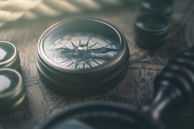
6 Photogrammetry Techniques for Drones That Achieve Survey-Grade Accuracy
Why it matters: Drone photogrammetry has revolutionized how professionals capture precise 3D data across industries from construction to archaeology. You can now create detailed maps, models and measurements using specialized flight patterns and camera techniques that deliver survey-grade accuracy.
The big picture: Modern photogrammetry software paired with the right drone techniques lets you generate professional results that rival traditional surveying methods at a fraction of the cost and time investment.
Disclosure: As an Amazon Associate, this site earns from qualifying purchases. Thank you!
Nadir Photography: The Foundation of Drone Photogrammetry
Nadir photography forms the cornerstone of successful drone photogrammetry projects. This straight-down shooting technique captures overlapping images that photogrammetry software uses to reconstruct accurate 3D models and orthomosaics.
Optimal Flight Patterns for Grid Coverage
Execute systematic grid patterns to ensure complete coverage of your survey area. Fly parallel flight lines with 70-80% forward overlap and 60-70% side overlap between adjacent strips. Plan your grid orientation perpendicular to prevailing winds for better stability. Use mission planning software like DroneDeploy or Pix4Dcapture to automate these patterns and maintain consistent altitude throughout the flight.
Camera Settings for Maximum Detail Capture
Configure your camera for maximum sharpness and detail retention during nadir flights. Set ISO to 100-200 to minimize noise while maintaining fast shutter speeds above 1/500s to prevent motion blur. Use aperture settings between f/4-f/8 for optimal lens sharpness. Enable manual focus set to infinity and shoot in RAW format to preserve maximum image data for processing.
Ground Control Point Integration
Position ground control points strategically across your survey area before launching your nadir photography mission. Place GCPs at the corners and center of your survey area with additional points every 500-1000 feet depending on accuracy requirements. Use surveyed targets with high contrast patterns that remain visible from your flight altitude. Record precise coordinates using RTK GPS equipment for survey-grade accuracy in your final deliverables.
Oblique Photography: Capturing Vertical Surfaces and Building Details
Oblique photography fills the gaps that nadir shots can’t capture, giving you comprehensive coverage of vertical structures like building facades, cliff faces, and infrastructure details. This technique complements your overhead imagery by providing the angular perspectives needed for complete 3D reconstruction.
Multi-Angle Image Acquisition Strategies
Orbit patterns around structures deliver consistent angular coverage while maintaining optimal image overlap. Execute circular flights at 30-45 degree camera angles, capturing images every 10-15 degrees of rotation. Double-grid missions with alternating oblique angles provide comprehensive coverage for large areas. Plan your flight lines at opposing 45-degree angles to ensure vertical surfaces receive adequate image capture from multiple viewpoints for robust photogrammetric processing.
Balancing Nadir and Oblique Shot Ratios
Maintain a 70:30 ratio of nadir to oblique images for optimal processing results in most architectural and urban mapping projects. This balance ensures your photogrammetry software has sufficient overhead coverage for accurate ground plane reconstruction while providing enough angled imagery for vertical detail capture. Increase oblique ratios to 50% when documenting complex structures like towers, bridges, or steep terrain where vertical surfaces contain critical measurement data.
Processing Considerations for Mixed Datasets
Calibrate camera parameters separately for nadir and oblique image sets since different angles create varying distortion patterns that affect bundle adjustment accuracy. Use masked processing workflows to exclude sky areas and irrelevant background elements that can confuse tie point matching algorithms. Process datasets in phases – start with nadir images to establish ground control, then integrate oblique shots gradually to maintain processing stability and identify alignment issues early.
Cross-Hatch Flight Patterns: Ensuring Complete Coverage and Accuracy
Cross-hatch flight patterns create dual grid coverage by flying perpendicular flight lines over your survey area. This technique significantly improves photogrammetric reconstruction quality by capturing each ground point from multiple viewing angles.
Creating Overlapping Flight Lines
Execute your first grid pattern with standard 70-80% forward overlap and 60-70% side overlap between adjacent flight lines. Plan your second grid perpendicular to the first, maintaining identical overlap percentages for consistent coverage density.
Position flight lines to ensure every ground point appears in images from both grid directions. Use mission planning software like DJI Terra or Pix4Dcapture to automate grid generation and maintain precise spacing. Configure waypoint altitudes to accommodate terrain variations while preserving consistent ground sampling distance across both patterns.
Adjusting Speed and Altitude for Optimal Results
Maintain consistent flight speeds between 15-25 mph to prevent motion blur while ensuring adequate image sharpness across both grid patterns. Set your altitude to achieve 2-5 cm ground sampling distance based on your accuracy requirements and camera specifications.
Reduce flight speed by 20% during windy conditions to maintain image quality and GPS accuracy. Configure your camera’s shutter speed to 1/1000s or faster to eliminate motion blur. Monitor battery consumption carefully since cross-hatch patterns require approximately 80% more flight time than single-grid missions.
Reducing Processing Time Through Efficient Planning
Process each grid pattern separately during initial alignment stages to reduce computational complexity and memory requirements. Merge the aligned datasets during dense point cloud generation to leverage the enhanced coverage without overwhelming your processing hardware.
Configure processing software to prioritize high-overlap areas where both grids intersect for improved tie point generation. Use masked processing workflows to exclude redundant imagery from low-priority areas. Schedule processing during off-peak hours since cross-hatch datasets typically require 2-3 times longer processing compared to single-grid surveys.
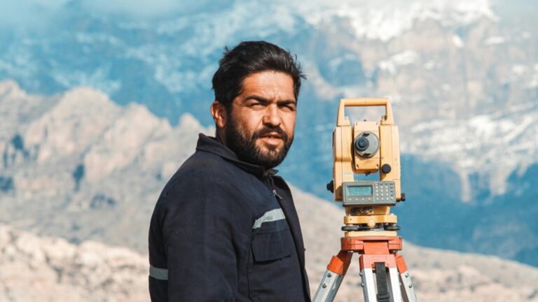
Ground Control Point Integration: Achieving Survey-Grade Accuracy
Ground control points transform standard drone photogrammetry into survey-grade mapping by providing absolute positioning reference data. This technique elevates your project accuracy from several meters to centimeter-level precision.
Strategic GCP Placement for Maximum Effectiveness
Position your GCPs at survey area corners and evenly distribute them throughout the project site for optimal triangulation. Place control points on flat, stable surfaces like concrete pads or painted markers that’ll remain visible throughout data collection. Establish one GCP per 5-10 acres for standard mapping projects, increasing density for complex terrain or high-accuracy requirements. Space GCPs 200-300 meters apart for consistent geometric strength across your survey area.
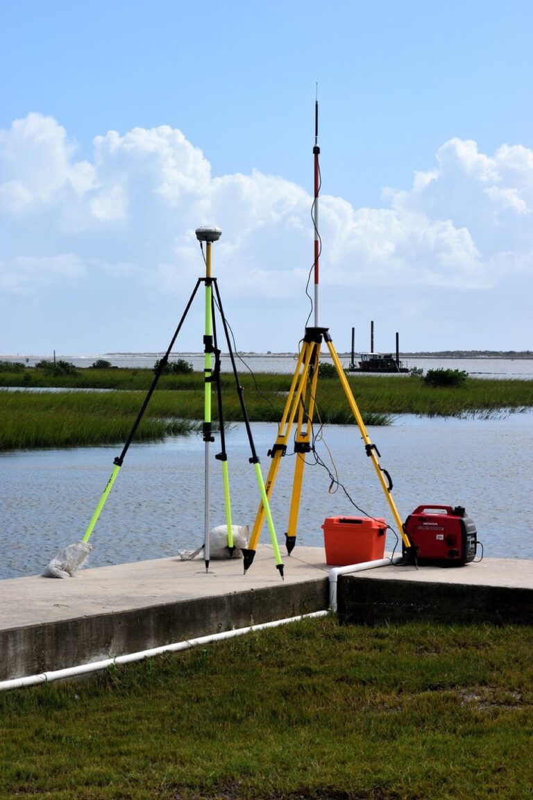
Equipment Requirements for Precise Measurements
Survey-grade GPS receivers with RTK capabilities deliver the centimeter-level accuracy needed for professional photogrammetry projects. Use dual-frequency GNSS units like Trimble R10 or Leica GS18 for reliable coordinate measurement under various field conditions. Deploy temporary targets made from reflective materials or spray-painted markers measuring 12-18 inches across for clear visibility in aerial imagery. Maintain 2-3 second observation times per GCP to ensure coordinate reliability and reduce measurement uncertainty.
Get precise location data on your Bluetooth-enabled device with the Garmin GLO 2. This receiver combines GPS and GLONASS for accuracy and offers up to 13 hours of battery life on a single charge.

Coordinate System Selection and Transformation
Select local coordinate systems that match your project requirements and client specifications for seamless data integration. Use State Plane Coordinate System zones for most US-based projects, or UTM coordinates for international work requiring global compatibility. Configure your photogrammetry software to handle datum transformations between WGS84 collection coordinates and final project systems. Apply geoid models like GEOID18 to convert ellipsoidal heights to orthometric elevations matching local benchmarks and existing survey data.
Multi-Temporal Photogrammetry: Monitoring Changes Over Time
Multi-temporal photogrammetry extends beyond single survey captures to track landscape evolution, construction progress, and environmental changes. You’ll create time-series datasets that reveal patterns invisible in standalone surveys.
Establishing Baseline Data Collection Protocols
Document your initial survey parameters meticulously since you’ll replicate them throughout the monitoring period. Record flight altitude, camera settings, overlap percentages, and GCP locations in a standardized data sheet. Create a comprehensive site map marking permanent reference features like buildings, large trees, and infrastructure that’ll serve as visual anchors. Establish consistent naming conventions for flights, images, and processed outputs to maintain dataset organization across multiple collection periods.
Maintaining Consistent Flight Parameters
Execute identical flight paths using saved mission files to ensure comparable image geometry between surveys. Maintain the same altitude, speed, and camera angle settings you used in your baseline collection. Monitor lighting conditions and schedule flights during similar times of day to minimize shadow variations that can affect change detection algorithms. Verify your drone’s GPS accuracy before each mission since positional drift can introduce false change signals in your comparative analysis.
Change Detection Analysis Techniques
Generate digital surface models (DSMs) from each time period and perform pixel-by-pixel elevation comparisons to identify vertical changes. Use difference mapping workflows in photogrammetry software like Pix4D or Agisoft to create color-coded change visualization maps. Apply statistical thresholds to filter noise from genuine changes, typically setting minimum change values at 2-3 times your vertical accuracy specification. Validate detected changes through field verification or high-resolution imagery comparison to distinguish real modifications from processing artifacts.
Close-Range Photogrammetry: High-Resolution Detail Capture
Close-range photogrammetry maximizes detail resolution by positioning your drone closer to subjects, enabling millimeter-level accuracy for architectural features, infrastructure inspection, and artifact documentation.
Low-Altitude Flight Planning Considerations
Altitude optimization requires flying between 10-30 feet above your target to achieve sub-centimeter ground sample distances. You’ll need shorter flight lines with reduced spacing to maintain consistent overlap ratios at close range. Mission segmentation becomes critical – divide complex structures into manageable sections to prevent GPS signal interference near buildings or terrain features. Plan multiple battery swaps since low-altitude flights consume more power due to increased maneuvering and slower speeds required for sharp imagery.
Managing Wind and Stability Challenges
Wind mitigation demands using sport mode sparingly and enabling maximum gimbal stabilization settings to counteract turbulence near structures. You’ll encounter increased wind shear at low altitudes around buildings, requiring reactive flight adjustments and maintaining minimum 5-foot clearances from vertical surfaces. Stabilization techniques include reducing flight speed to 2-3 mph in windy conditions and using tripod mode for stationary shots. Monitor real-time gimbal feedback to detect stability issues before they affect image quality.
Post-Processing for Enhanced Detail Resolution
Resolution enhancement starts with enabling ultra-high quality reconstruction settings in your photogrammetry software, typically increasing processing time by 300-400% but delivering superior edge definition. You’ll achieve optimal results using mesh refinement algorithms that interpolate additional surface detail from overlapping imagery. Texture optimization requires adjusting sampling rates to match your target output resolution – use 2-4x oversampling for technical documentation projects. Apply noise reduction filters selectively to preserve genuine surface detail while eliminating reconstruction artifacts common in close-range datasets.
Conclusion
Mastering these six photogrammetry techniques will transform your drone surveys from basic aerial photography into professional-grade data collection. You’ll achieve survey-grade accuracy while reducing costs and timeframes compared to traditional methods.
The key to success lies in combining multiple techniques strategically. Whether you’re monitoring construction progress with multi-temporal analysis or capturing architectural details through close-range methods your results will depend on proper planning and execution.
Start with nadir photography and ground control points to build your foundation. Then gradually incorporate oblique imaging cross-hatch patterns and specialized techniques as your projects demand higher precision and detail.
Your investment in learning these methods will pay dividends across industries from archaeology to construction management. The technology continues evolving but these fundamental techniques remain the cornerstone of professional drone photogrammetry.
Frequently Asked Questions
What is drone photogrammetry and how does it work?
Drone photogrammetry is a technique that uses specialized flight patterns and camera settings to capture overlapping aerial images, which are then processed by software to create precise 3D models, maps, and measurements. The process combines multiple photographs taken from different angles to reconstruct accurate three-dimensional representations of terrain, buildings, and objects with survey-grade accuracy.
What overlap percentages should I use for drone photogrammetry surveys?
For optimal results, maintain 70-80% forward overlap between consecutive images and 60-70% side overlap between flight lines. These overlap percentages ensure sufficient image redundancy for accurate 3D reconstruction and help eliminate gaps in coverage. Higher overlaps may be necessary for complex terrain or when maximum accuracy is required.
What are Ground Control Points (GCPs) and why are they important?
Ground Control Points are precisely surveyed reference markers placed throughout the survey area to enhance accuracy and achieve survey-grade precision. GCPs transform standard drone photogrammetry from meter-level to centimeter-level accuracy by providing known coordinate references. They should be placed on stable surfaces and distributed evenly across the project area for optimal triangulation.
What’s the difference between nadir and oblique photography in drone surveys?
Nadir photography captures straight-down images essential for creating accurate orthomosaics and top-down views. Oblique photography captures angled images of vertical surfaces and building details that nadir shots miss. A recommended ratio is 70% nadir to 30% oblique images for comprehensive 3D reconstruction that captures both horizontal and vertical features effectively.
How close should I fly my drone for detailed photogrammetry work?
For close-range photogrammetry requiring millimeter-level detail, fly at altitudes between 10-30 feet above the subject. This low-altitude approach maximizes ground sample distance resolution but requires careful planning to manage wind effects and ensure image stability. Segment complex missions into manageable sections for better control and coverage.
What camera settings work best for drone photogrammetry?
Use the lowest possible ISO (typically 100-200), fast shutter speeds to prevent motion blur (minimum 1/500s), and moderate aperture settings (f/4-f/8) for optimal depth of field. Shoot in RAW format when possible and disable auto-focus during flight to maintain consistent image quality. Adjust settings based on lighting conditions and flight speed.
What is multi-temporal photogrammetry and what are its applications?
Multi-temporal photogrammetry involves capturing the same area at different time intervals to monitor changes over time. Common applications include tracking construction progress, monitoring erosion, detecting landscape changes, and assessing environmental impacts. Consistent flight paths and survey parameters are crucial for accurate change detection and comparison between datasets.
How do cross-hatch flight patterns improve photogrammetry results?
Cross-hatch patterns involve flying overlapping grid patterns in perpendicular directions, capturing each ground point from multiple angles. This technique significantly improves 3D reconstruction quality by providing better geometric constraints and reducing reconstruction errors. Execute each grid pattern separately during processing, then merge datasets for enhanced accuracy and detail.
What software considerations are important for processing mixed nadir and oblique datasets?
When processing mixed datasets, calibrate camera parameters separately for different shooting angles and use masked processing workflows to improve accuracy. Handle nadir and oblique images in separate chunks initially, then merge them during final processing. This approach prevents processing artifacts and ensures optimal reconstruction quality from diverse image angles.
How can I validate the accuracy of my photogrammetry results?
Validate results through field verification using independent survey measurements, compare generated models with known reference data, and use checkpoints separate from your GCPs. For change detection projects, distinguish real modifications from processing artifacts through ground-truthing. Regular accuracy assessments help maintain quality standards and identify areas for improvement in your workflow.